Symbol Elements Overview
Creating a symbol involves drawing the symbol itself and also defining the related information shown in the following illustration.
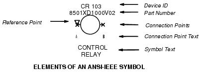
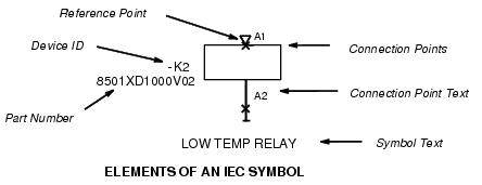
- Device ID - A device ID tag must be defined for intelligent symbol types. The rest of the device ID is added to this tag at the time the symbol is placed on the drawing. In the illustration above, CR is used as the tag for control relay device IDs. The rest of the ID is filled in automatically when the symbol is placed in a drawing and might consist of consecutive numbers, page number, line number, or a combination of these (determined in the Project Parameters dialog when a new project is created).
- Insertion Point - An insertion point must be defined. This point will be positioned on the cursor when the symbol is placed in the drawing.
- Connection Points - These points determine where wires will break when the symbol is placed on a wires or when a wires is drawn through the symbol. Wires must be drawn to connection points on symbols to allow the connections to appear in the wire list.
- Connection Point Text - If desired, text can be defined that will automatically label the connection points when the symbol is placed (such as A and B terminations on a relay coil).
- Symbol Text - This is optional, additional text which will appear with the symbol. Symbol text can be fixed text, or it can be configured to prompt the user for information (Amp values, for example) when the symbol is placed.
- Part Number (Optional) - You can enter a part number during symbol creation so that this part number will be automatically prompted whenever the symbol is placed.
Symbols created with this procedure become part of a Promis.e symbol catalog and can be accessed at any time during drawing creation. The symbol will be stored in the first catalog search path.